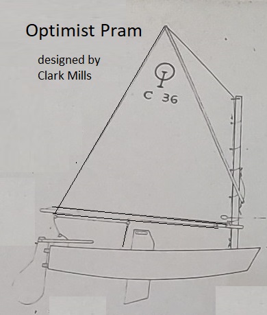
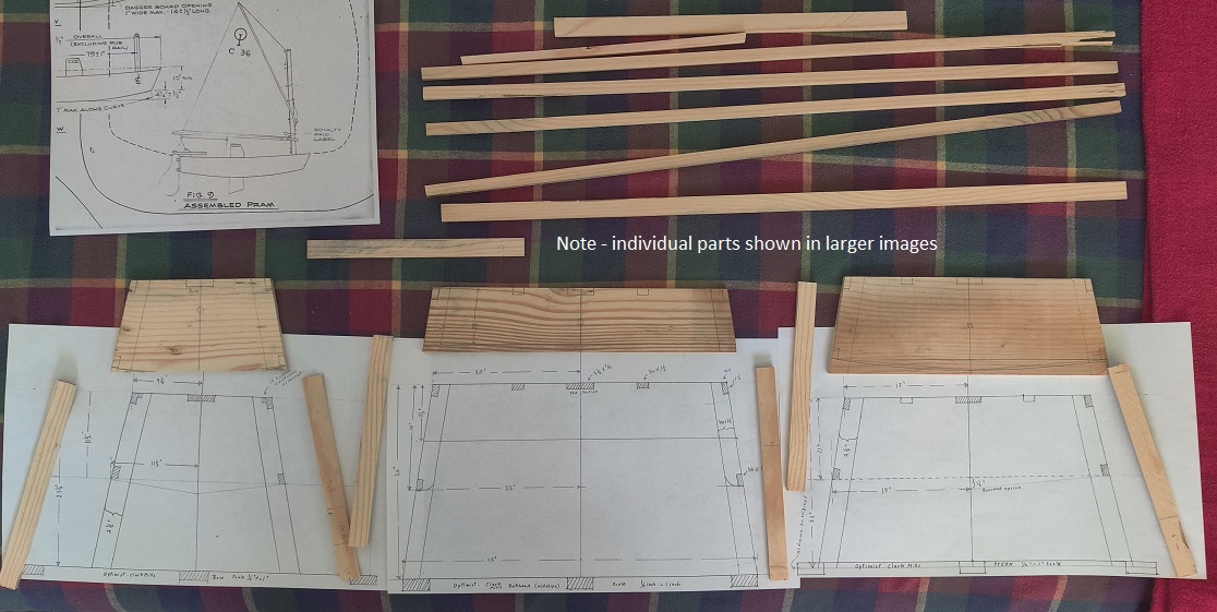
line drawing of the Optimist Pram as designed in 1948 by Clark Mills of Florida, USA
line drawing of the Optimist Pram as designed in 1948 by Clark Mills of Florida, USA
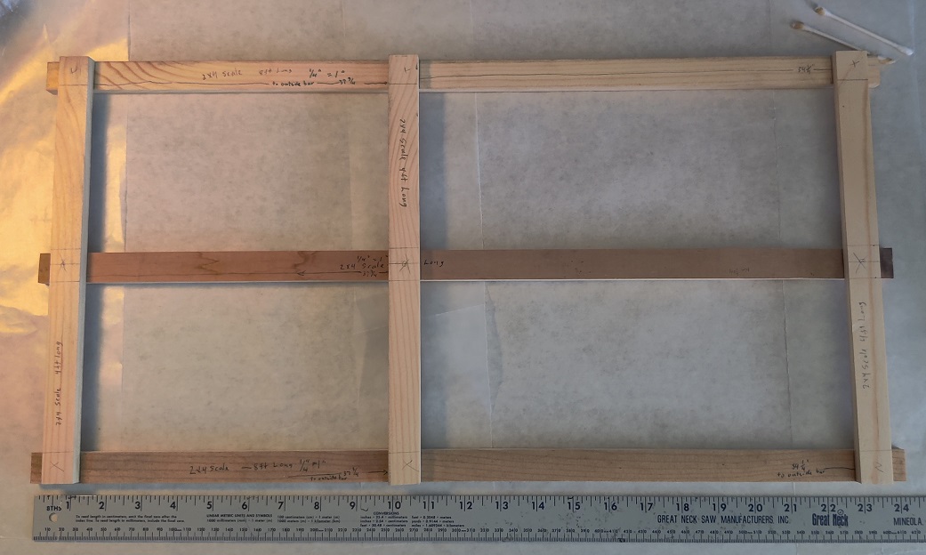
Opti Model building base
This is a photo of the building base for the model .
It is a 1/4 inch = 1 inch scale
each of the boards are scaled to be equal to standard 2x4s
s_model_build_base
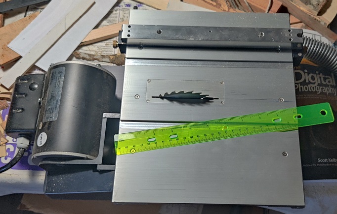
This little table saw was made for cutting fine little pieces for models
It is a Byrnes Model Machine, made in Florida.
s_model_little_table_saw
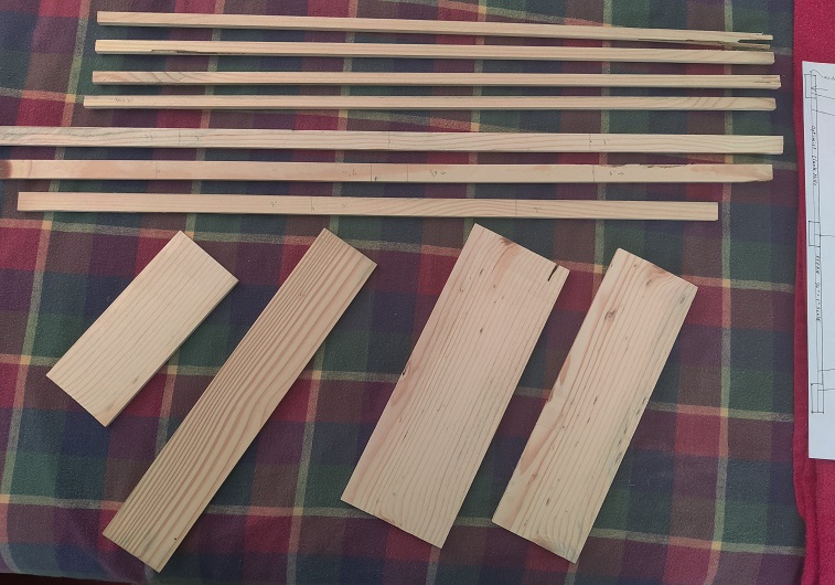
The raw parts, cut to scale mostly using the tiny table saw.
The original wood was a nominal 1x (3/4 inch) piece of white pine.
These were marked to their eventual shape, then cut to size and shape.
s_model_raw_parts
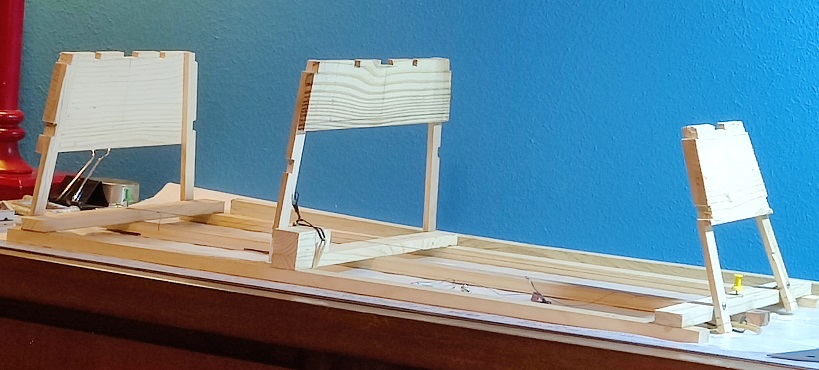
Model transverse parts - ready to be glued to their legs
s_model_parts_ready_to_trim
![]()
bow transom ready to trim - displayed on the corresponding plan
xxx
s_bow_transom_ready_to_trim
![]()
The middle transverse part ready to trim - displayed on the corresponding plan
s_model_middle_transverse_ready_to_trim
![]()
The stern transom part ready to trim displayed on the corresponding plan.
s_stern_transom_part_ready_to_trim
![]()
Bow Transom and Middle section glued to their legs
Weights were placed on the parts to hold them against the legs while the glue cures.
s_bow_transom_middle_section_glued
![]()
Stern transom glued to its legs
with weights on them to hold them while the glue cures
s_model_stern_transom_glued
The building base diagram - showing the transverse parts attached
building_base_diagram
 - - - -
The way the glued pieces connect to the building base to make the pram. - - - - - - - Top view as per plan
building_base_used - - - - - - - - - - top_view_01
frames first up on frame
OptiModel_2023_07_07_frames_1st_up
Middle station and bow transom braced-up on the building base
OptiModel_2023_07_08_frames_braced
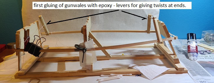
first gunwale glue in place with twists at ends
the next day I discovered that the epoxy did not hold well this time. A couple of the ends released.
OptiModel_2023_07_09_first_gunwale_glue
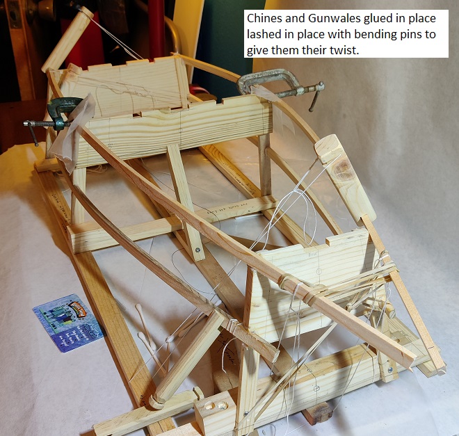
Gunwales and Chines tied in place and just glued
OptiModel_2023_07_10_gunwales_chines_gluing
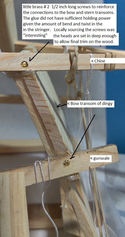
littel brass No. 2 screws 1/2 inch long added to secure ends of all stringers
OptiModel_2023_07_11_screws_added
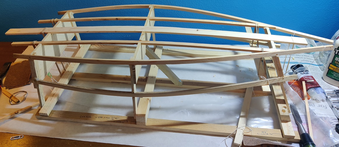
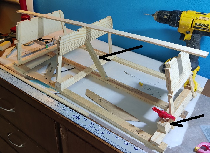
all stringers on - including the keelson and botom stiffeners
Here you can see, with the chines temporarily left long protruding in front of the bow transom, (the ghost of a sharpie).
Clark Mills original thought of making a sharpie style boat, but he needed to keep no more than 8 ft overall for cost reasons,
so he just -sawed off- the front and made a pram. (information from an interview he gave years later)
OptiModel_2023_07_11_all_stringers_on_02
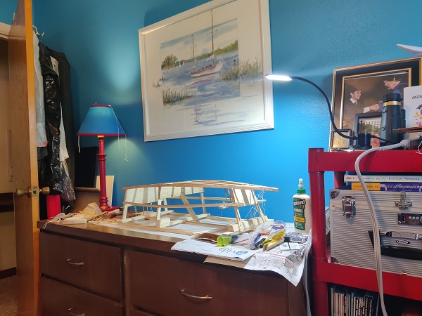
Building area in NE bedroom
Creating the stringers and major cutting and shaping is done in the workshop, not bedroom.
Fitting and gluing together is done in the bedroom.
OptiModel_2023_07_11_building_area
- - - - - - - - - - - - - - -
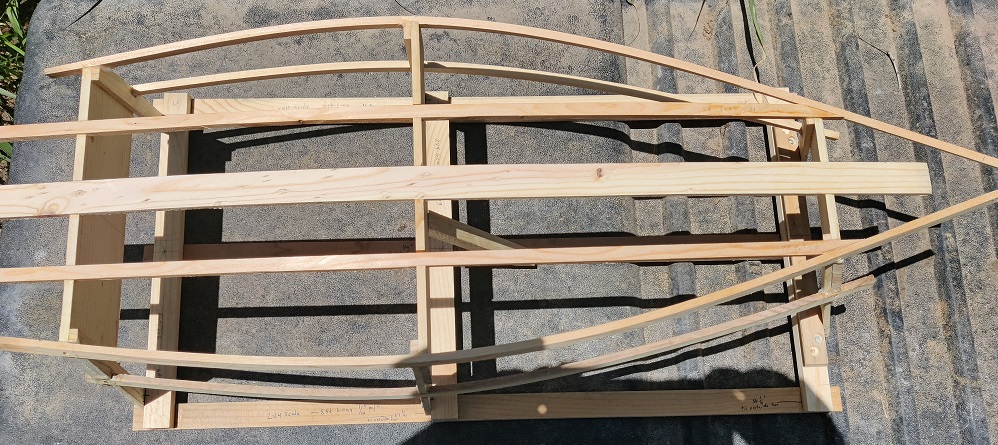
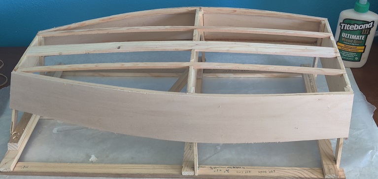
all the tie-downs removed. The glue is holding and it is ready for trimming
OpMod_2023_07_12_stringer_glue_hard
frame with ends trimmed before any sanding
OpMod_2023_07_12_stringer_ends_trimmed_1
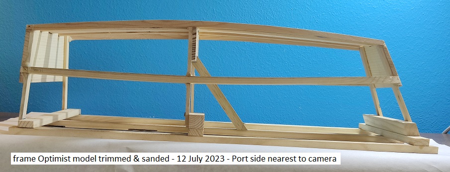
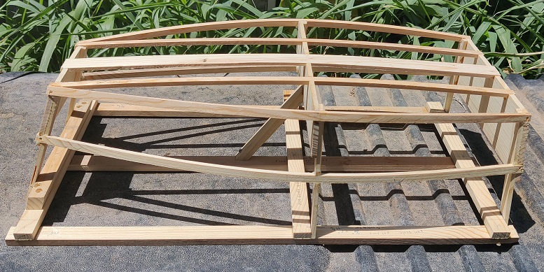
side photo of frame trimmed and sanded
OpMod_2023_07_12_side_trim_sanded
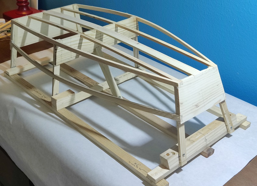
view of fore quarter - frame trimmed and sanded
Very nearly ready for sides and bottom to be glued on.
OpMod_2023_07_12_forequarter_trim_sanded
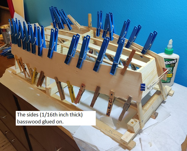
The 1/16th thick basswood glued to the sides and clamped, using Titebond III glue
OpMod_2023_07_13_sides_glued_on
clamps (clothes pins) off sides securely glued on, not yet trimmed
OpMod_2023_07_14_sides_on
Sides on and bottom trimmed to the Chines
The trimming was more difficult than expected, but it got done without damage to the project, or to me.
OpMod_2023_07_14_sides_bottom_trimed
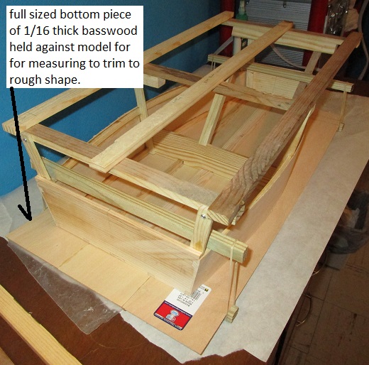
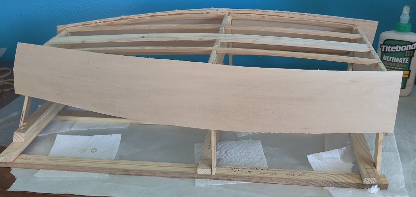
Previously edge glued 1/16 inch basswood held against the model frame
for marking to be cut to rough shape before it is glued on.
After marking it was cut out to rough shape on a band saw.
OpMod_2023_07_14_bottom_scribed_to_trim
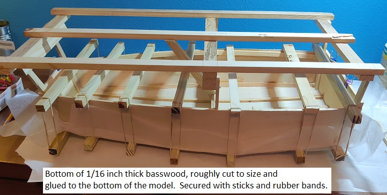
Bottom glued on and secured for glue to dry.
Sitting right-side-up
OpMod_2023_07_14_bottom_glued
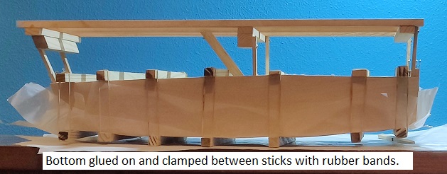
OpMod_2023_07_14_bottom_glued_clamped
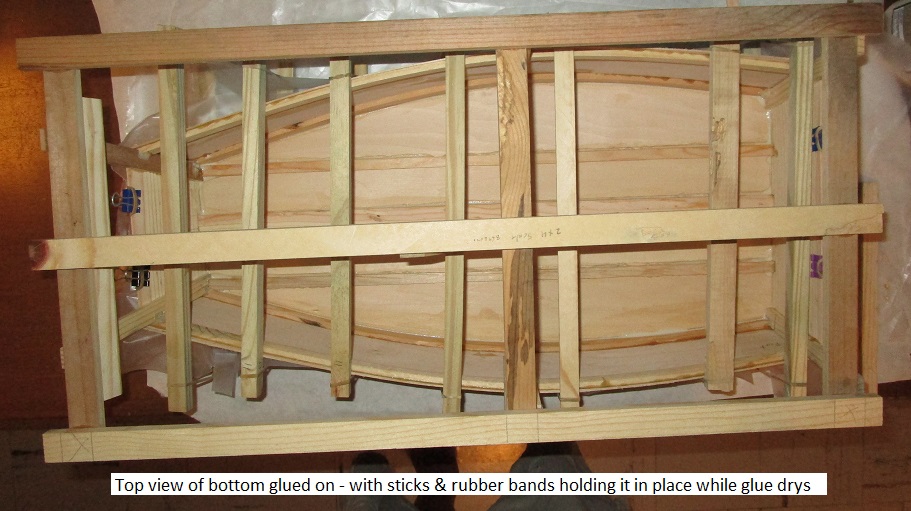
Bottom glued on - top view
OpMod_2023_07_14_top_view_bottom_glued
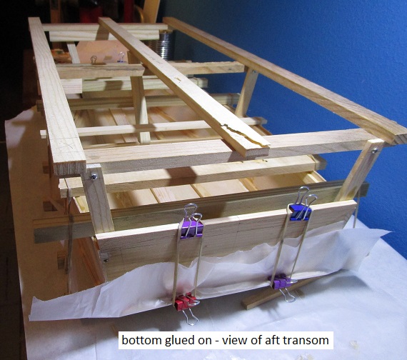
Bottom glued on.
Small binder clamps and rubber bands hold the bottom firmly to the transom
Note that the building base frame is still attached to the model.
OpMod_bottom_glued_aft_view
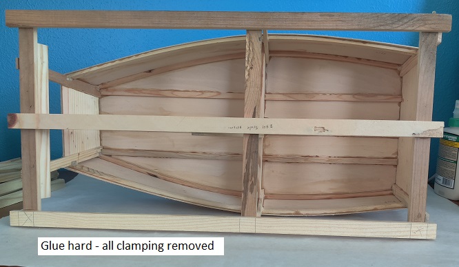
All bottom bottom clamping removed. Ready to trim edges
OpMod_2023_07_15_all_bottom_clamping_removed
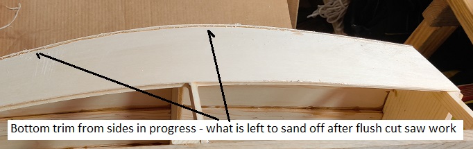
Edges of bottom trim flush to sides process.
OpMod_2023_07_15_bottom_trimming
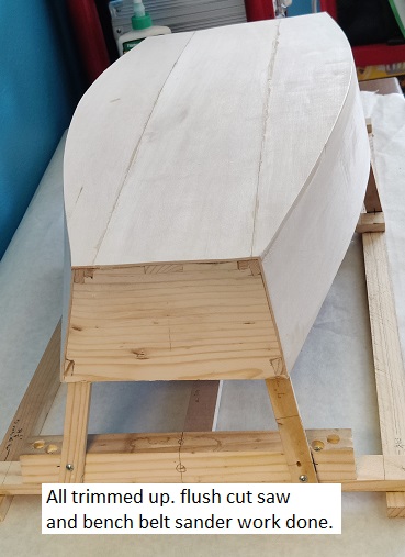
Bottom all trimmed up, sides, stern transom, bow transom.
OpMod_2023_07_15_all_trimmed
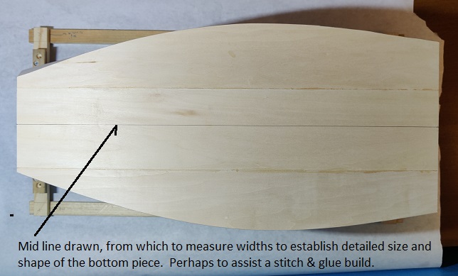
mid-line drawn on bottom.
measurements outfrom this line will define the shape of the bottom.
Note that the building base frame is still attached to the model for stability while handling.
OpMod_2023_07_15_mid_line
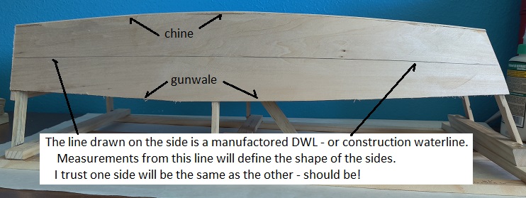
Line drawn on the side for a construction DWL.
measurements out from this line will define the shape of the side.
To make these measurements the model must be removed from the building base and
the rough edges of the upper sides will be smoothed to the gunwales.
OpMod_2023_07_15_side_DWL_established
Note that the shapes of the bow and stern transoms are
very clearly drawn out on the original plans and do not need to be re-calculated.
- - - - - - - - - - - - - - -
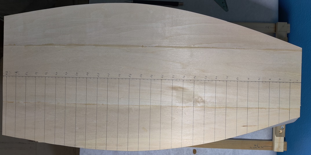
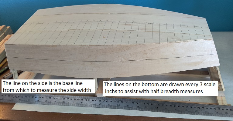
mid-line drawn on bottom - then measured and lined
The numbers on the mid-line are scale 1 inch apart
The lines off the numbers are scale 3 inches apart
measurements out from the mid-line along the lines drawn out from the mid-line will define the shape of the bottom.
Now to measure each of these lines to create a table of measurements so the shape can be reproduced.
OpMod_2023_07_17_bottom_half_lined.jpg
The lines out from the mid-line are measured
with a digital caliper - see measurements and calculations to make a full sized Bottom in the link below
The numbers in the farthest Right column are full breadth inches -
at the distance from the Front (Bow Transom) at 3 inch intervals.
The last measure at inch 86 is the measure of the Stern Transom.
OpMod_2023_07_19_lines_for_measuring
The Bottom measurements and Bottom calculations for a Full Sized boat.
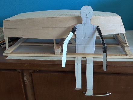
Jack Tar II is of an adult some 5ft 7 inches tall at the same scale as the model.
Shown to give a view of how big the Optimist pram dinghy is compared to an adult person.
Note that the model is still attached to the building frame.
OpMod_2023_07_19_JackTar_2
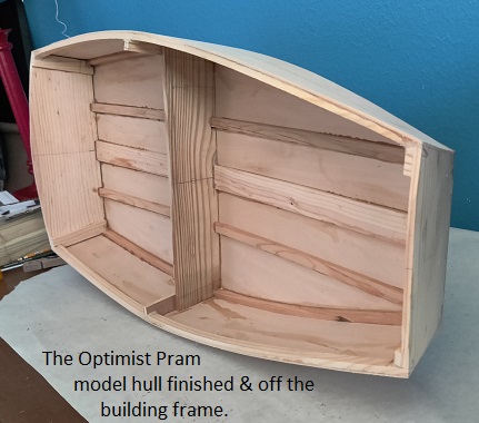
The hull of the Optimist pram model is essentially done.
It is finally off the building frame, and the sides at the gunwales are trued up smooth.
OpMod_2023_07_19_Opti_Model_fin_oblique_bow_view
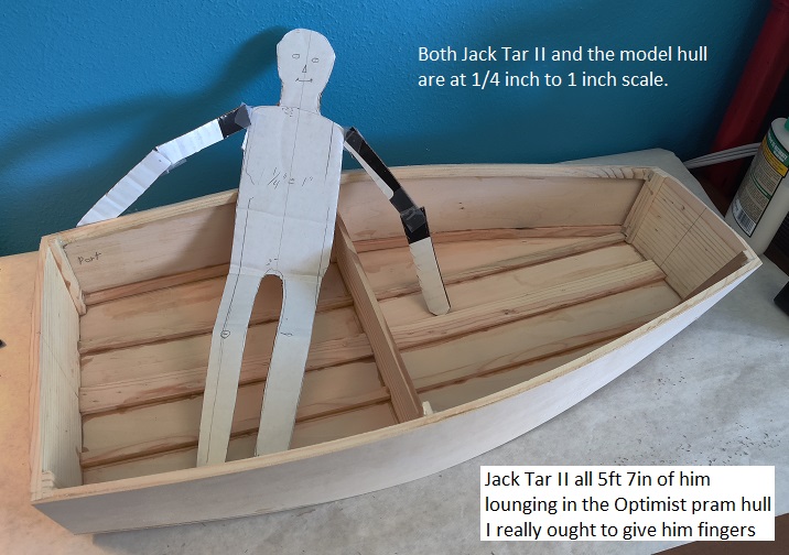
Jack Tar II (scale height would be 5 ft 7 inches) lounging in the hull of the Optimist model.
He is here to demonstrate the size of the hull compared to an adult human.
OpMod_2023_07_19_JackTar2_lounging_in_hull
The next step is to measure the shape of the side panel
and create a table of measurements so full sized sides can easily be made.
Then finish out the inside with a mast step, mast partner, and
perhaps a mast and sail - oh yes, rudder & tiller, and dagger board or other lateral resistance (keel function).
.
The Sides measurements for a Full Sized boat.
Bottom measurements for making a Full Sized boat
- - - - -
Bottom calculations - TMI - too much information, and maybe less accurate.
= = = = = = = = = = = = = = = = = = = = = = = = = = = = = = = = = = = = = = = = = = = = = = =
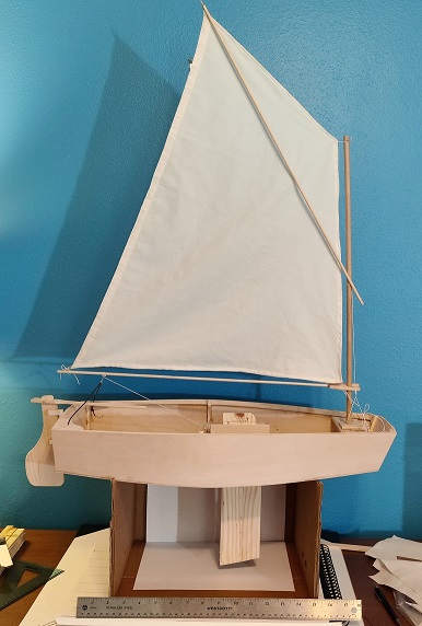
Optimist pram Model almost finished
The model is essentially finished in the picture above. There are a few fine points to be added,
but it is essentially finished. The rudder and tiller are added and workable. The daggerboard is in its slot.
The first paper sail has been replaced by a really fine cotton sail, sewen up by Mona.
- - more later when the project is done - -
- - - - end - - -
Illustrated plans and instructions for making a full sized Optimist pram using conventional methods (much how the model was made).
- - - - - - - - - - - - - - - - - - - - - - - - - - - - - - -
Making a model of a Saboteer pram
Home Page at www.stexboat.com
-